Control Loop
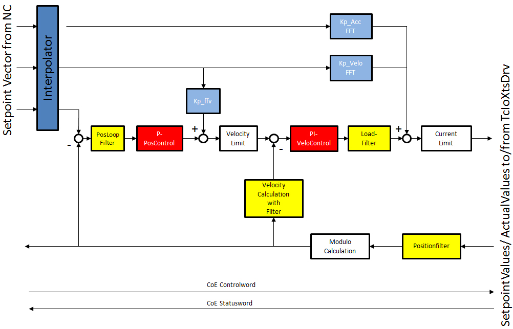
The yellow blocks are filtering blocks and these blocks dictate what signal the soft drive controller will see and operate on. The red blocks are the control loops themselves and operate on the values given by the yellow blocks. The white blocks are limits and fixed constants such that even when the control loop requests more than the maximum values these limits will prevent damage to the components by limiting the commanded velocity or current. The blue blocks are feed forward values. These values dictate how much of a look ahead the system will implement. | |
The system contains multiple sets (copies) of the same parameters. The use of these multiple sets of parameters can be enabled and the control loops will automatically switch through the various parameter sets according to specific rules. By default 2 sets of parameters are implemented. Moving Parameters that are used while the set point velocity is greater than zero and stand still parameters that are used after the Set Velocity has been zero for 100ms. (The time is adjustable). A third set and fourth set of parameters become available when “Areas” are implemented. These are generally used for the curves. The system can have 4 sections of track defined as an “Area” of the track. Any time a mover is within any of these “Areas” the Area parameters are used. There is one set of Moving Area Parameters and one set of Area Stand Still Parameters. The Area configuration also includes a Ramp distance. The ramp distance allows for the switch from the normal moving gains to the Area gains to be linearized over a distance. This is done so that the control loop gains do not have a step change, but are ramped in and out. Parameters that have a stopped/standstill setting will indicate this by having _standstill after the parameter name and parameters that have an area setting will have _area after their name. | |
